


 By
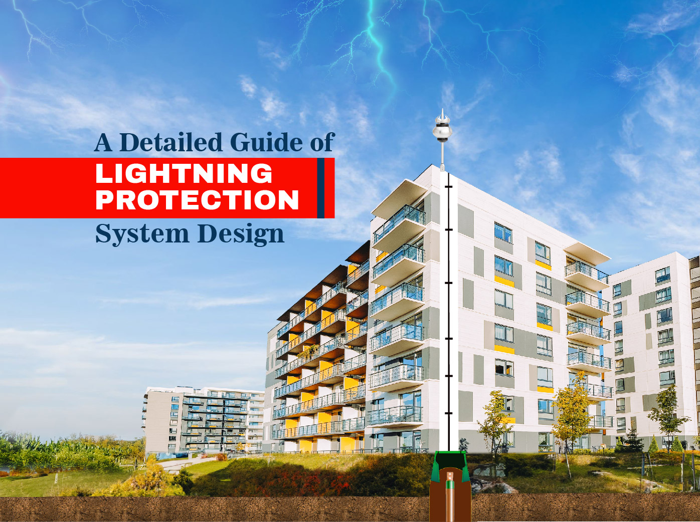
Designing a lightning protection system (LPS) is a sequence, not a product choice. You establish how much risk the structure carries, that fixes the protection level, and the protection level then fixes every geometric number in the design — how far apart the air terminations sit, how many down conductors you need, and how they are spaced. Get the sequence right and the hardware selection is almost mechanical. Get it backwards — pick a lightning arrester first and design around it — and you end up with a system that is compliant on paper and exposed in practice.
This guide walks the sequence as it is applied under IEC 62305 (adopted in India as IS/IEC 62305), with earthing to IS 3043.
The three parts of a lightning protection system
Everything in an external LPS belongs to one of three subsystems, and a strike passes through all three in order.
1. Air termination — intercepting the strike
Rods, masts, a mesh across the roof, or catenary wires — whatever presents a preferred attachment point so the strike lands where you decided rather than on a chimney, a chiller or a parapet. Ashlok’s range covers air terminals, conventional Franklin rod and mesh systems and ESE terminals. Selection is covered in types of lightning rods.
2. Down conductors — carrying the current
Conductors that take the current from the air termination to earth on the shortest, straightest route available. Sharp bends and loops raise the inductive voltage drop and invite side flashes, so routing is a design decision, not an installation one. On framed buildings the structural steel or welded reinforcement is often used as a natural down conductor, provided electrical continuity was established during construction.
3. Earth termination — dispersing the energy
The electrode arrangement that gets the current into the soil. Type A (individual rods or plates at each down conductor) suits small structures; Type B (a ring or foundation electrode) is the normal choice for anything large or tall, because it holds every down conductor at a common potential. Ashlok supplies maintenance-free earthing electrodes, copper bonded rods and backfill compound for this stage.
Two further elements are part of any real design even though they sit outside those three: equipotential bonding, which ties incoming services and internal metalwork to a common reference so the current cannot side-flash indoors, and surge protection, which deals with the transient that couples into the wiring regardless of how good the external system is.

Step 1 — Risk assessment
This is the step most often skipped, and it is the one that determines everything downstream. A risk assessment to IEC 62305-2 compares the risk the structure faces against a tolerable level, and tells you whether protection is required and to what class. The inputs are:
- Lightning ground flash density for the location — strikes per square kilometre per year.
- Collection area — derived from the structure’s height, length and width, plus nearby structures that shield it.
- Construction — metal, concrete or combustible; roof and wall materials.
- Occupancy and contents — number of people, evacuation difficulty, whether there is anything explosive, flammable or irreplaceable inside.
- Services entering — power, telecom and data lines are both a strike path in and a damage route.
- Consequential loss — loss of life, loss of public service, loss of cultural heritage, economic loss.
This assessment is what a lightning protection study or lightning risk analysis refers to. It is also the basis of any honest cost-benefit analysis: IEC 62305-2 lets you compare the annualised cost of protection against the annualised cost of the loss it prevents, which is usually how a system gets approved on an industrial site where nobody is legally compelled to fit one.
Step 2 — Fix the protection level (LPL I to IV)
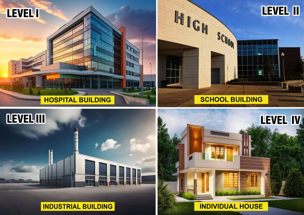
The assessment outputs a Lightning Protection Level, and with it the corresponding LPS class. Class I is the most stringent, Class IV the least. The level is not a preference — it is what sets the geometry of the whole design:
| Class of LPS | Rolling sphere radius | Mesh size | Typical down-conductor spacing | Typically applied to |
|---|---|---|---|---|
| Class I | 20 m | 5 × 5 m | 10 m | Explosives, chemical plant, hospitals, critical infrastructure |
| Class II | 30 m | 10 × 10 m | 10 m | Industrial plant, high-occupancy and high-value buildings |
| Class III | 45 m | 15 × 15 m | 15 m | Ordinary commercial and residential buildings |
| Class IV | 60 m | 20 × 20 m | 20 m | Low-risk structures with low consequential loss |
Read the table left to right and the logic is obvious: a stricter class means a smaller sphere, a tighter mesh and more down conductors — i.e. fewer unprotected gaps and more parallel paths to earth.
Step 3 — Position the air terminations
Three methods are permitted, and a real design normally uses more than one on the same building.
- Rolling sphere. Imagine rolling a sphere of the class radius over the structure. Anything the sphere touches can be struck and must be protected or bonded. This is the general method — it works on any shape and it is the one that correctly exposes upper corners, edges and rooftop plant.
- Mesh. A conductor grid of the class mesh size laid over a flat roof, with perimeter conductors at the edges. Simple and economical for large flat roofs.
- Protection angle. A cone of protection below a rod or mast. Convenient for small structures and masts, but the permitted angle shrinks as height increases, so it stops being usable on tall structures — which is why rolling sphere governs on towers.
For a lightning mast protecting an open area — a tank farm, a substation yard, a stadium or a storage compound — the design question is the reverse: you know the volume that must be covered, and you are solving for mast height and position using the rolling sphere. Expect more than one mast; a single tall mast almost never covers a real yard.
On structures taller than about 60 m, air termination is also required on the upper sides, not only the roof, because side flashes become significant. See how tall buildings are protected from lightning.
Worked examples for this step — sphere sag between rods, the protected radius of a mast and mesh sizes by class: lightning protection layout: rolling sphere, protection angle and mesh.
Step 4 — Lay out the down conductors
- Distribute them around the perimeter at the spacing your class allows — never fewer than two on any structure.
- Keep routes short and straight. Avoid loops; every loop adds inductance and raises the voltage that drives a side flash.
- Add horizontal ring conductors at intervals up tall structures so the current shares between routes.
- Use the structural frame or welded rebar where continuity has been established and proven — it gives you many well-distributed paths for nothing.
- Provide a test joint on each down conductor above the earth termination so continuity and earth resistance can be measured later.
- Maintain separation distance from internal metalwork, or bond to it. There is no third option.
Step 5 — Design the earth termination
Start from measured soil resistivity, not from an assumed figure — electrode count and length follow directly from it (the formulas are in how to calculate earth electrode resistance). A ring (Type B) arrangement is preferred for anything large or tall; Type A rods are acceptable on small structures. Where resistivity is high, increase electrode length, add electrodes, or use a low-resistivity backfill compound around them rather than simply driving more rods into the same bad soil.
The lightning earth must be bonded to the electrical earth — separate, unbonded earths are a classic and dangerous error, because a strike raises one to a high potential while the other stays where it was, and the difference appears across whatever is connected between them.
Make buried joints by exothermic welding, keep electrodes accessible through an earth pit chamber with a test link, and verify against the limits in acceptable earth resistance values as per IS 3043. Method for the measurement itself: how to check earthing resistance.
Step 6 — Bonding and surge protection
Bond every incoming service — power, water, gas, telecom, data, cable armour — at the entry point, and repeat bonding up the height on tall structures. Then coordinate surge protection devices: Type 1 at the service entrance, Type 2 at distribution boards, Type 3 at sensitive equipment. An external LPS without SPDs saves the building and loses the contents. SPD guide here.
Step 7 — Documentation, testing and maintenance
A design is not finished at installation. The deliverable set should include the risk assessment, the protection class and the reasoning, the layout drawings, the bill of materials with standards referenced, commissioning continuity and earth resistance readings, and a planned inspection interval. Re-inspect after any known strike and after any work that touches the roof, the facade or the risers.
A note on design software and calculators
Rolling-sphere and risk-assessment tools are genuinely useful for the arithmetic and for producing drawings, and most manufacturers and standards bodies offer one. They do not replace judgement. A tool will happily return a compliant answer from wrong inputs — an assumed soil resistivity, a flash density for the wrong region, a collection area that ignores the tower next door. Validate the inputs, and have the output reviewed by someone who has stood on the roof.
Common design mistakes
- Choosing hardware before doing the risk assessment.
- Treating the lightning earth and the electrical earth as separate systems.
- Too few down conductors, or all of them on one face of the building.
- Looped and dog-legged conductor routes taken for cosmetic reasons.
- Rooftop plant, aerials and handrails left outside the protected volume and unbonded.
- Assuming soil resistivity instead of measuring it.
- No test joints, no chamber covers — so the system can never be verified again.
- External protection installed with no SPDs behind it.
Need a design reviewed?
Ashlok manufactures the complete lightning protection and earthing range in Chennai and works with consultants, EPC contractors and plant engineers across India. Send us the structure details, soil resistivity and protection level and we will come back with a layout and a bill of materials. Call +91 94440 87356 or contact us.
Frequently asked questions
What standard is used for lightning protection system design in India?
IS/IEC 62305 — the Indian adoption of IEC 62305 — is the design standard, with Part 2 covering risk management and Part 3 covering physical damage to structures. Earthing is designed to IS 3043.
What is a Level 4 lightning protection system?
Class IV is the least stringent LPS class — a 60 m rolling sphere, a 20 × 20 m mesh and roughly 20 m down-conductor spacing. It is applied to structures whose risk assessment shows low consequential loss. It is not a shortcut: if the assessment returns Class II, building to Class IV is simply an under-designed system.
How many down conductors does a building need?
It follows from the perimeter and the class spacing, with a minimum of two on any structure. A 60 m perimeter at Class III (15 m spacing) needs four; the same building at Class I (10 m) needs six.
What is the difference between lightning protection design and a lightning protection study?
The study is the risk assessment — it establishes whether protection is needed and to which class, and often carries the cost-benefit case. The design is what follows: the layout, geometry, materials and earthing that deliver that class.
Can I use the building’s steel structure as a down conductor?
Yes, and on framed buildings it is usually the better answer — provided electrical continuity through the frame or the welded reinforcement was established and verified during construction. It cannot normally be introduced retrospectively.
Does an ESE terminal change the design method?
It changes how the air termination is positioned and sized, but not the rest of the sequence. Risk assessment, protection level, down conductors, bonding, earthing and SPDs all still apply. See the ESE lightning arrester guide.
Related reading
- Lightning Arrester Design for Buildings
- How Are Tall Buildings Protected From Lightning?
- Types of Lightning Rods
- Lightning Protection System: Complete Guide
- Earthing & Lightning Protection Cost in India
- Lightning Protection for Solar Panels
